Data Flow Modelling in Verilog
Verilog Language is a very famous and widely used programming language to design digital IC In this verilog tutorial level of abstraction has been covered. To get familiar with the dataflow and behavioral modeling of combinational circuits in Verilog HDL Background Dataflow Modeling Dataflow modeling provides the means of describing.
2
Verilog code for 21 MUX using data flow modeling.
. An OR gate is a logic gate that performs a logical OR operation. Full Adder in Dataflow model. Half adder is a combinational arithmetic circuit that adds two numbers and produces a sum bit S and carry bit C as the output.
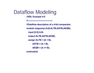
Dataflow modeling in Verilog allows a digital system to be designed in terms of its function. Verilog full adder in dataflow gate level modelling style. The dataflow level shows the nature of the flow of data in continuous assignment statements.
Continuous delivery is a value proposition net. In defining Data Flow Modeling a designer has. To help accurately predict these challenging flows we offer a wide range of models for gas liquid solid particle flows and even DEM to get you the most accurate results.
Dataflow modeling uses continuous assignments and keyword to share. Verilog code for AND gate using data-flow modeling. Behavioral Modelling and Timing.
Iverilog is the Verilog compiler to run Verilog programs. Data flow modeling. The data network is used in Verilog HDL to.
Dataflow modeling utilizes Boolean equations and uses a number of. A logical OR operation has a high 1 output when one or both of the gates inputs are high 1. There are three types of modeling for Verilog.
Vvp is the command to run the Verilog code. While the gate-level and dataflow. Module AND_2_data_flow output Y input A B.
But before starting to code we need proper knowledge of basic logic gates in Verilog. In Verilog Behavioral models contain procedural statements which control the simulation and manipulate variables of the data types. We would again start by declaring the module.
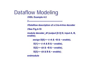
Gate level modelling is compared with Data flow modelling with the help of few exampleslin. However in complex design designing in gate-level modeling is a challenging and highly complex task and thats where data-flow modeling provides a powerful way to implement a design. Dataflow modeling makes use of the functions that define the working of the circuit instead of its gate structure.
Module fulladder input a input b input cin output s output cout. Then we use assignment. They are Dataflow Gate-level modeling and behavioral modeling.
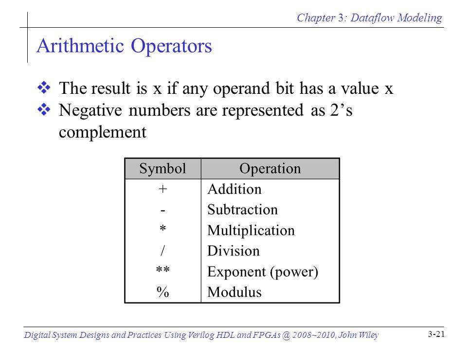
Instead of using directly in data flow we use operations such as Bit-Wise AND Multiply Modulus Plus - Minus Logical AND etc in Data Flow modelling. Learn to design Combinational circuits using data Flow modelling. Dataflow modeling has become a popular design approach as logic synthesis.
The two basic logic gates are AND and OR gates in which the name suggested.
Verilog Tutorial

Chapter 3 Dataflow Modeling Digital System Designs And Practices Using Verilog Hdl And 2008 2010 John Wiley 3 1 Chapter 3 Dataflow Modeling Ppt Download
Chapter 3 Dataflow Modeling Digital System Designs And Practices Using Verilog Hdl And 2008 2010 John Wiley 3 1 Chapter 3 Dataflow Modeling Ppt Download
Verilog Tutorial
Chapter 3 Dataflow Modeling Digital System Designs And Practices Using Verilog Hdl And 2008 2010 John Wiley 3 1 Chapter 3 Dataflow Modeling Ppt Download

Verilog Programming Series 2 To 4 Decoder Youtube


Comments
Post a Comment